
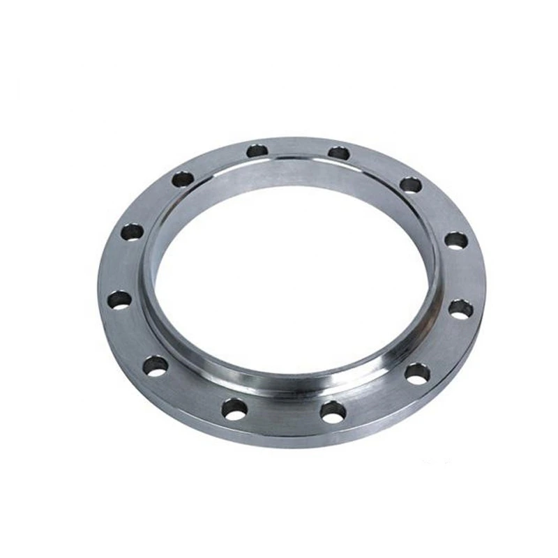
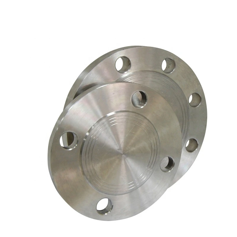
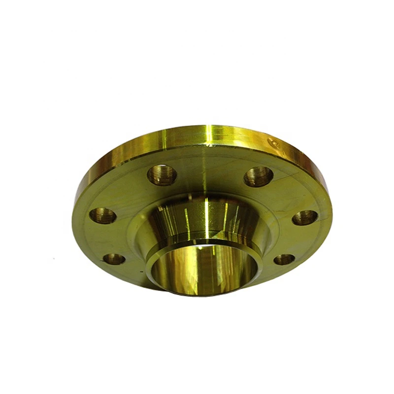
ASME B16.5 Weld Neck Flange for Oil and Gas
For industrial sourcing
Prepare a clearer RFQ
Include the details below so RELIA can understand the part and discuss the next step with you.
- Drawing, sample, or reference standard
- Material grade and preferred process
- Dimensions, tolerances, and surface finish
- Application, target quantity, and destination
Production timing, packing, and shipping terms are confirmed for each project after specifications and trade terms are agreed.
-
Surface TreatmentPolishedApplicationIndustrial Equipment
-
Bolt Hole Diameter1/2"Bolt Hole Quantity4
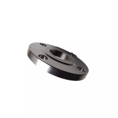
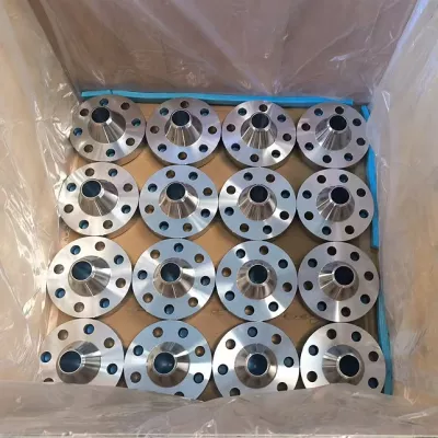
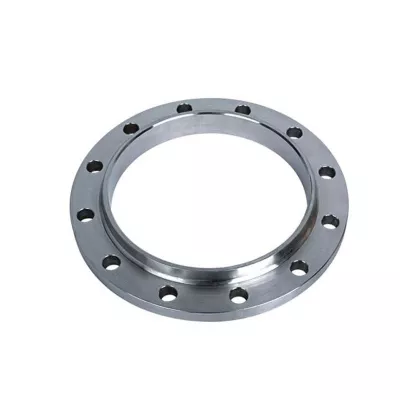
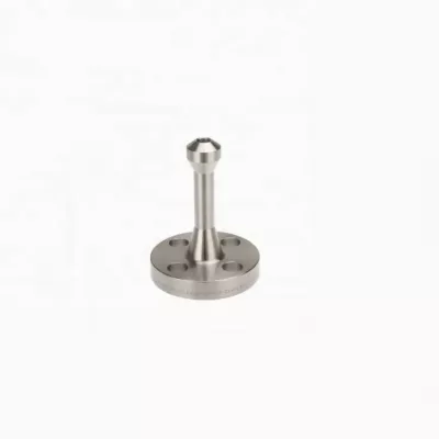
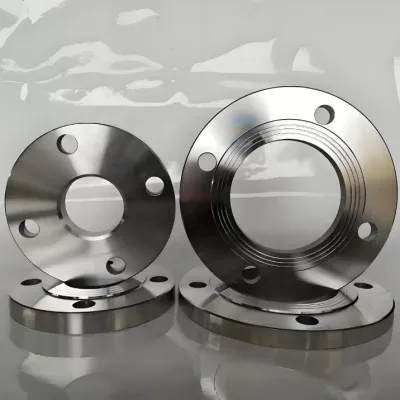
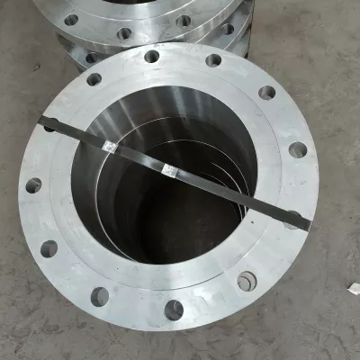
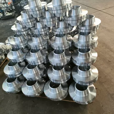
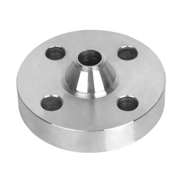
This ASME B16.5 weld-neck flange is presented for oil and gas piping with forged and polished references. Four material categories and nine flange types appear in the actual selections. Define the specific weld-neck supply and its governing requirements before assigning a class, bore or joint specification.
Verify B16.5 scope for the selected flange
Choose the individual nominal size, dimensional system and material grade. The 1/2–120-inch range label does not confirm availability at each size or establish that every selection falls within the cited standard. Obtain the applicable B16.5 edition, component scope and accepted pressure-class basis.
Request neck profile, bore, end preparation and mating pipe wall, together with facing, gasket seating, flange thickness and outside dimensions. Agree tolerances on the supply drawing. Alternative flange types require their own functional geometry; the weld-neck title cannot define every recorded construction.
Coordinate the neck joint and bolting pattern
The table records four bolt holes of 1/2-inch diameter. Confirm those values against the selected size and drawing, adding bolt circle, mating flange, bolting and gasket requirements. Check alignment, weld access and assembly space without carrying the same drilling arrangement across all variants.
Obtain the complete material specification, condition, heat traceability and certificates for the chosen Alloy Steel, Aluminum, Carbon Steel or Stainless Steel option. Verify actual forging, production and weld-end inspection records. Define polished surfaces, measurable finish acceptance and protection during handling and delivery.
Set an oil and gas operating envelope
Provide medium composition, contaminants, pressure, temperature, cycling, corrosion and external loads. High-pressure wording supplies no numerical class and no sour-service approval. Obtain acceptance for the selected material, flange and joint, then agree welding, support, inspection, testing, marking and material, manufacturing, dimensional and finish documentation in the quotation.
Technical information for every product inquiry
Prepare the requirement before final product confirmation.
The product page is a starting point. Drawings, samples, interfaces, materials, quantities and acceptance requirements are reviewed before stock matching or custom production is confirmed.
Discuss this product in your project context.
Share the available drawing, sample, reference, target quantity and application information. Unknown items can remain open for review.