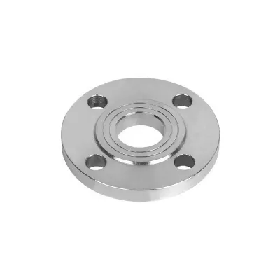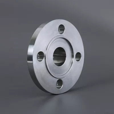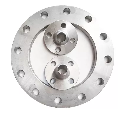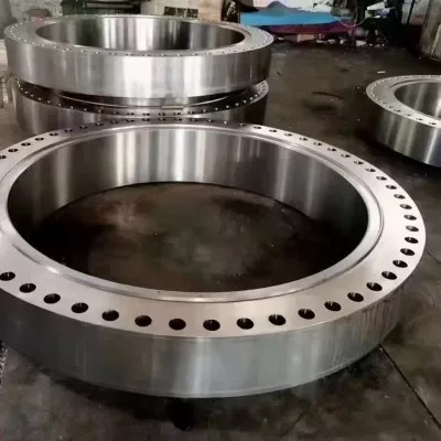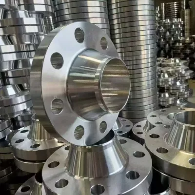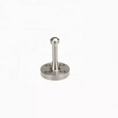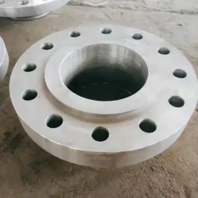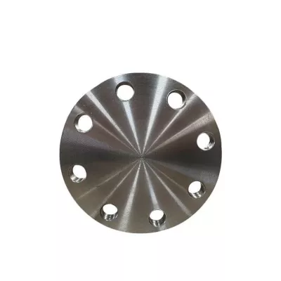

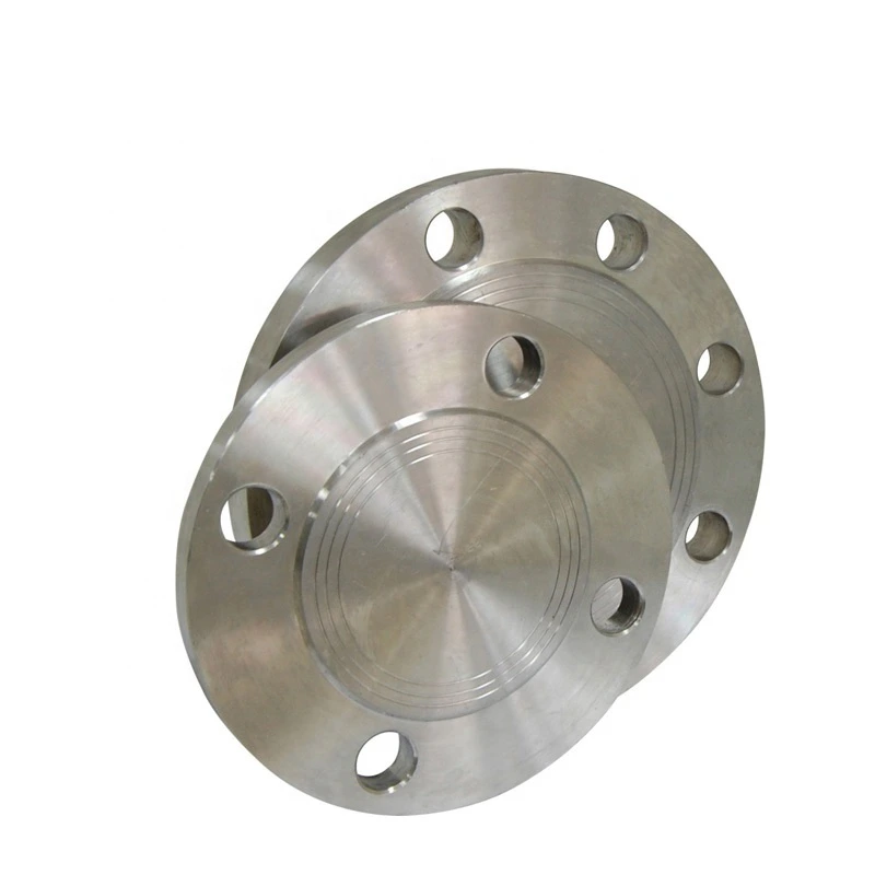
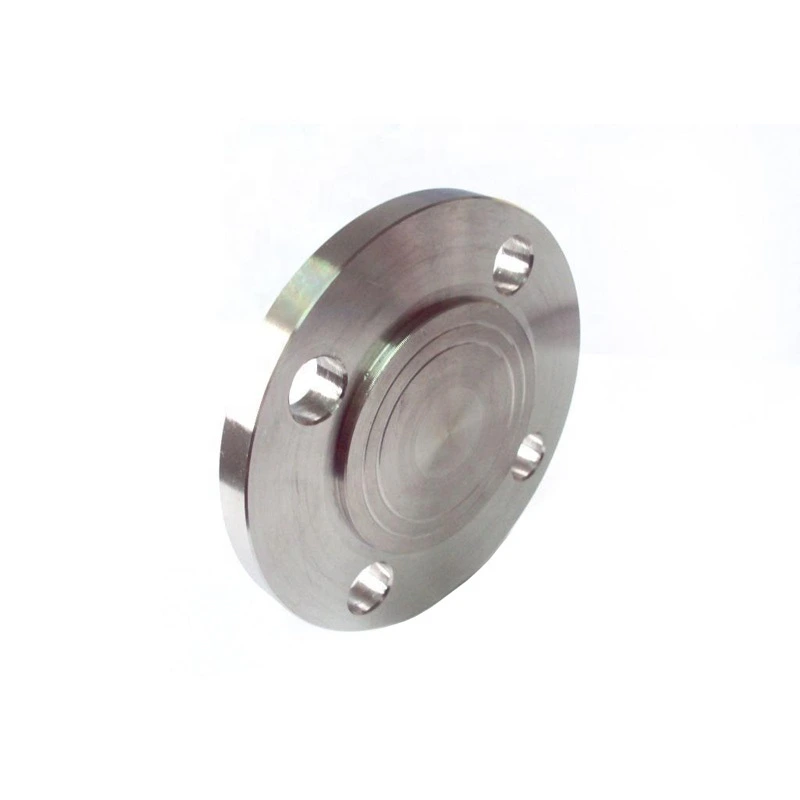
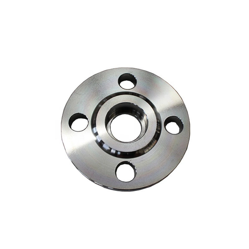
A105 Carbon Steel Lap-Joint Flange for Industrial Piping
For industrial sourcing
Prepare a clearer RFQ
Include the details below so RELIA can understand the part and discuss the next step with you.
- Drawing, sample, or reference standard
- Material grade and preferred process
- Dimensions, tolerances, and surface finish
- Application, target quantity, and destination
Production timing, packing, and shipping terms are confirmed for each project after specifications and trade terms are agreed.
-
Surface TreatmentPolishedApplicationAgricultural Irrigation, Air Conditioning, Chemical Industry, Construction, Environmental Engineering, Fiber Optic Co MMunication, Food And Beverage, HVAC, Mining, nuclear power, Oil And Gas, paper industry, Pharmaceutical, Power Generation, Shipbuilding, Steel Industry, Textile Industry, Wastewater Treatment, water supply, Industrial Equipment
-
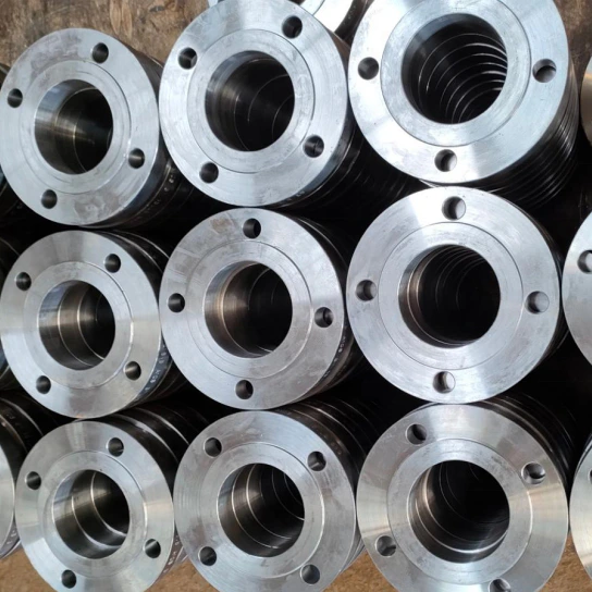
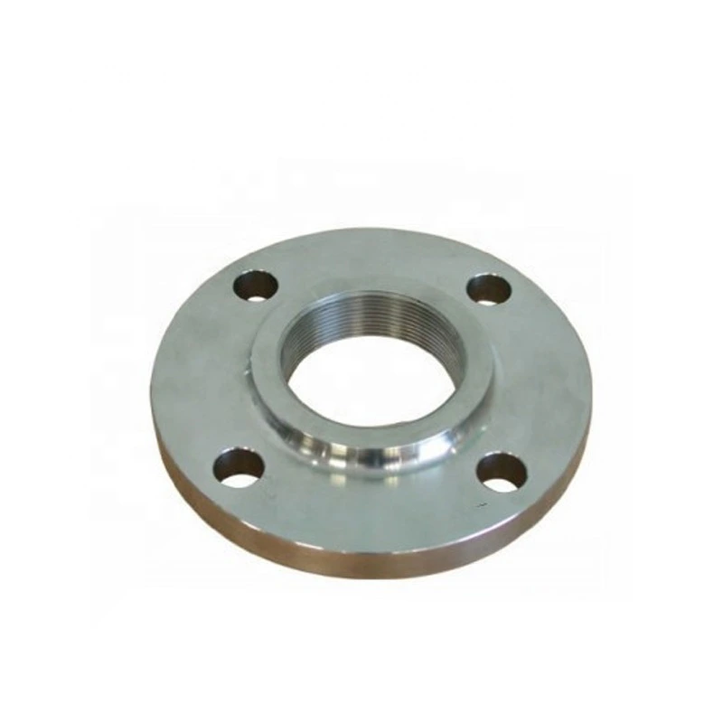
Bolt Hole Diameter1/2"Bolt Hole Quantity4
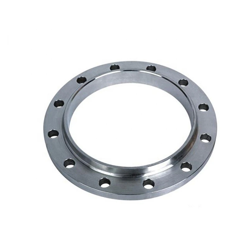
This A105 carbon steel lap-joint flange enquiry follows the B16.5 and polished title references for industrial piping. It addresses the carbon lap-joint configuration within a wider record. Confirm the actual assembly and face arrangement before applying the title specifications to an order.
Select the lap-joint configuration and mating assembly
The 36 variants combine four materials with nine flange types. Materials are Alloy Steel, Aluminum, Carbon Steel and Stainless Steel; types include integral, weld neck, slip-on, socket-weld, lap-joint, threaded, blind, orifice and spectacle blind. Carbon and lap-joint title attributes do not describe every alternative.
Clarify RF, FF and Raised Face wording through the selected assembly drawing. Identify which component and contact surface each term describes. Specify mating components, their materials and dimensions, and what is included in supply rather than assuming all face labels apply to the same body.
Approve dimensions, A105 supply and polished acceptance
Select one nominal size from the half-inch to 120-inch option and state its convention. Request outside dimensions, thickness, bore, contact geometry, bolt circle and tolerances. Allocate the listed four half-inch bolt holes to that drawing instead of using them as universal drilling across the range.
Obtain the complete material designation and condition, governing A105 and B16.5 documents and editions, and actual component conformity scope. Confirm the production route, certification and traceability. Define measurable polished-surface criteria, mating interfaces, sealing, bolting, examination and delivery protection.
Establish the industrial rating and operating evidence
Choose a pressure class and obtain its documented material/temperature rating basis. State actual medium composition, pressure and temperature limits, cycles, exposure and loads. The broad industry list does not establish approval for every service. Agree the selected assembly, face, drilling, material and inspection/testing package against the intended conditions before accepting supply.
Technical information for every product inquiry
Prepare the requirement before final product confirmation.
The product page is a starting point. Drawings, samples, interfaces, materials, quantities and acceptance requirements are reviewed before stock matching or custom production is confirmed.
Discuss this product in your project context.
Share the available drawing, sample, reference, target quantity and application information. Unknown items can remain open for review.