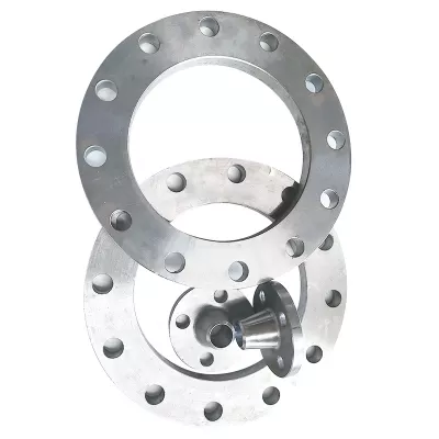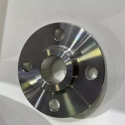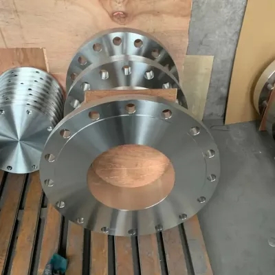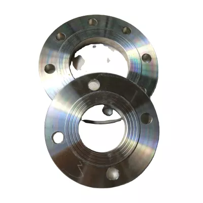
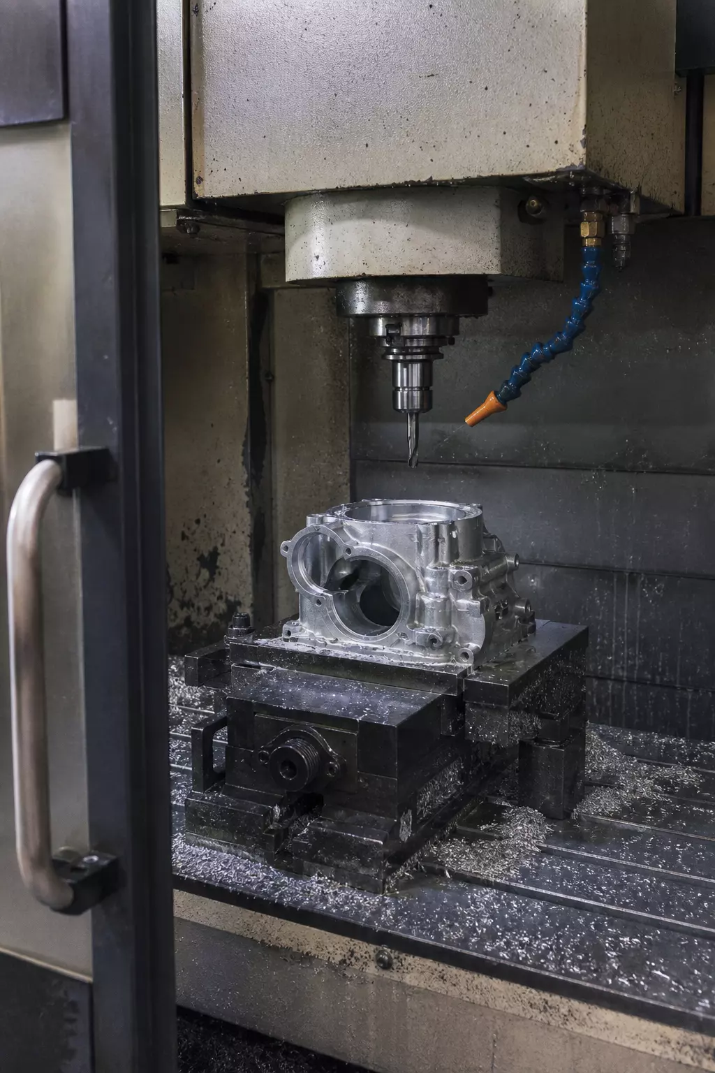

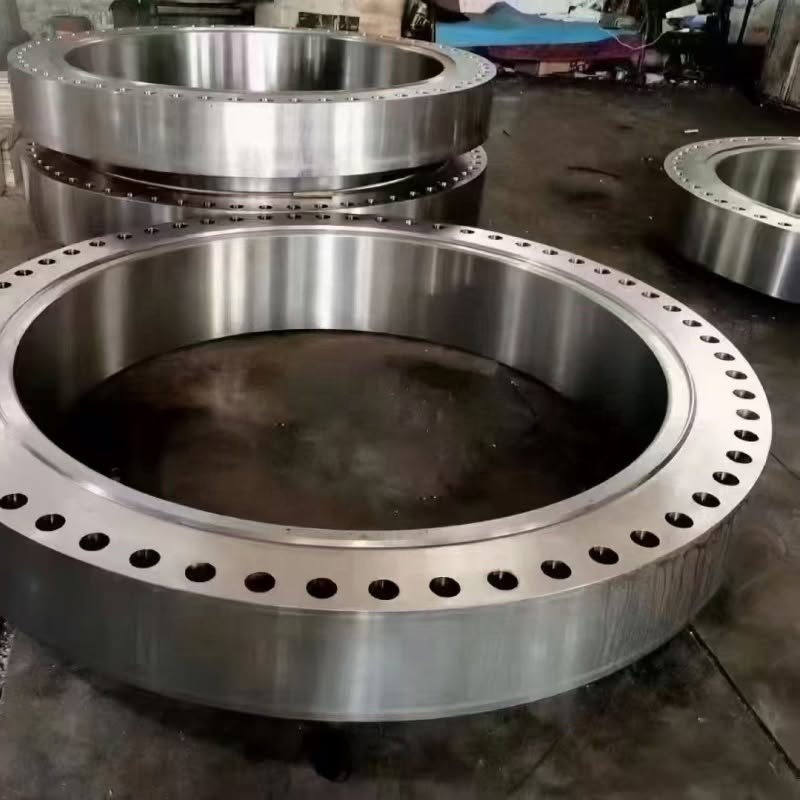
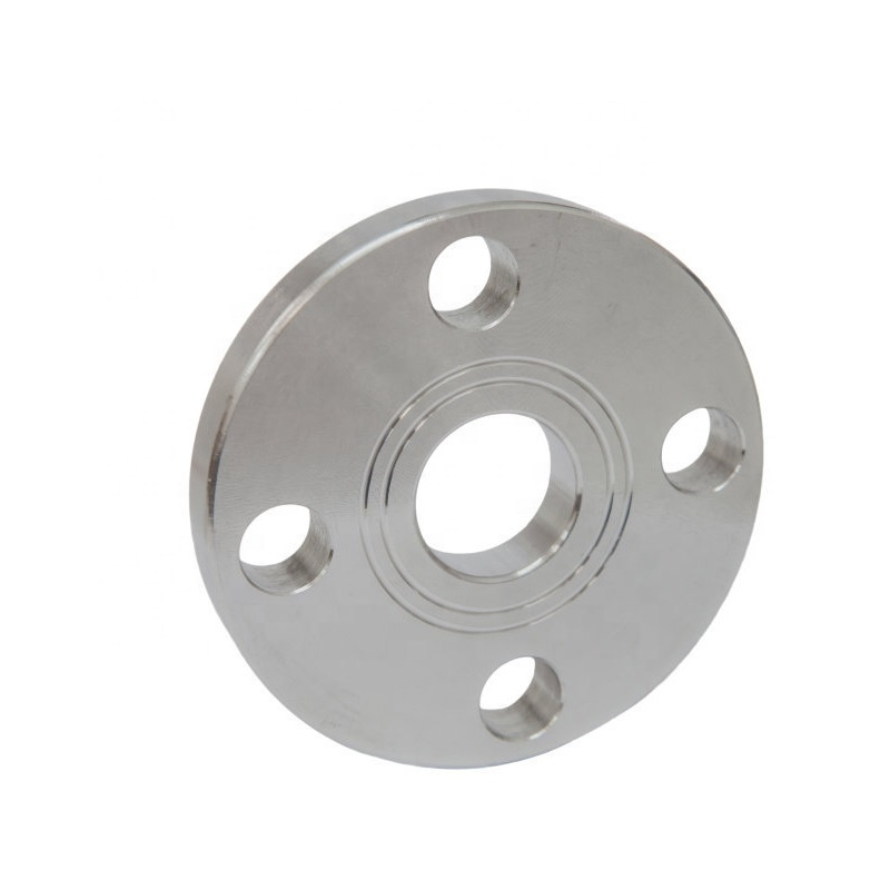
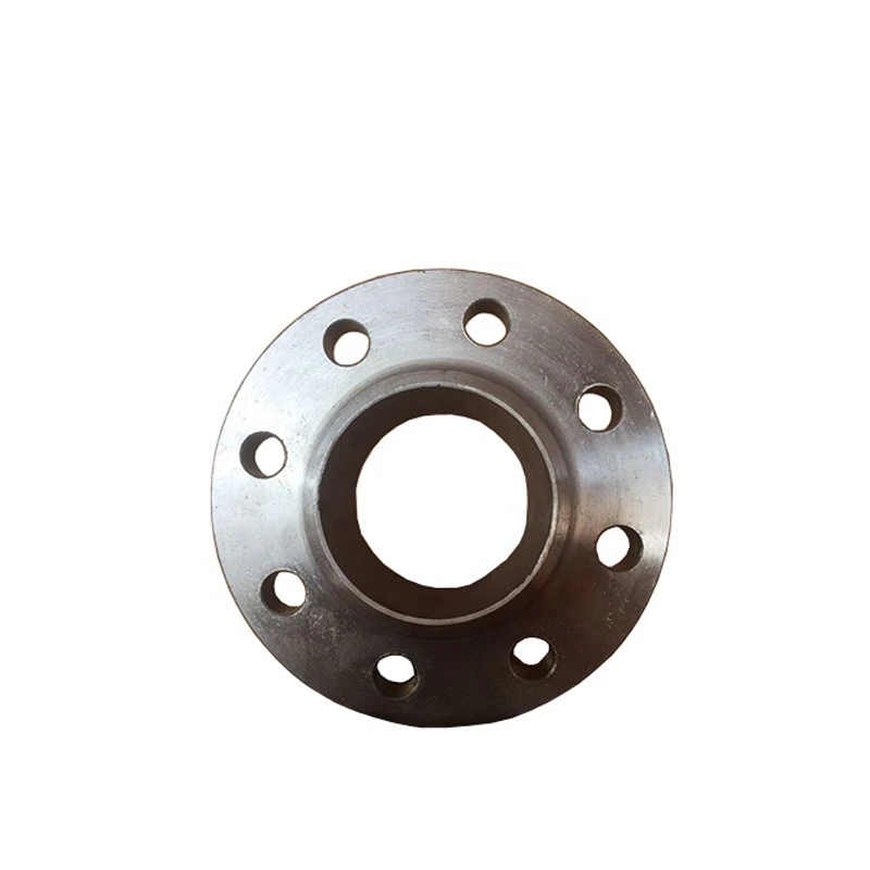
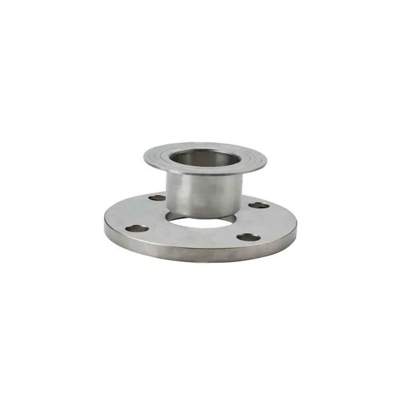
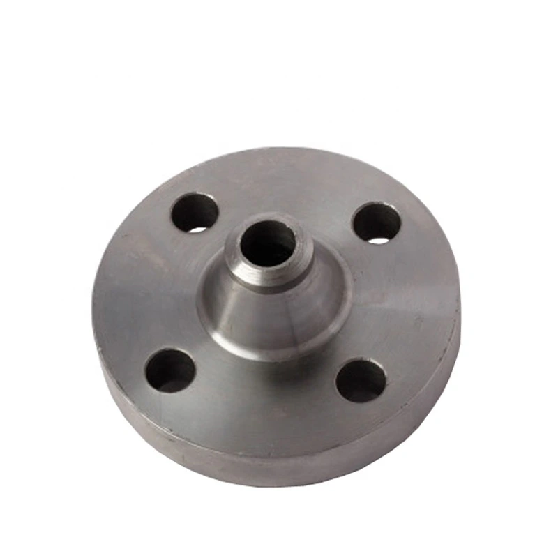
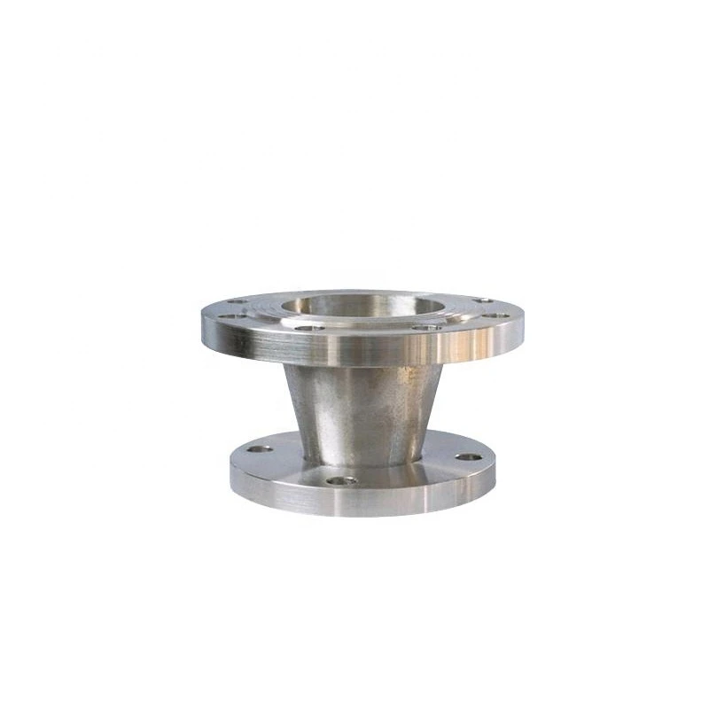
ASTM A694 F65 Weld Neck Flange for Equipment
For industrial sourcing
Prepare a clearer RFQ
Include the details below so RELIA can understand the part and discuss the next step with you.
- Drawing, sample, or reference standard
- Material grade and preferred process
- Dimensions, tolerances, and surface finish
- Application, target quantity, and destination
Production timing, packing, and shipping terms are confirmed for each project after specifications and trade terms are agreed.
-
Surface TreatmentPolishedApplicationIndustrial Equipment
-
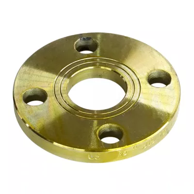
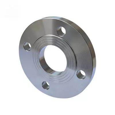
Bolt Hole Diameter1/2"Bolt Hole Quantity4
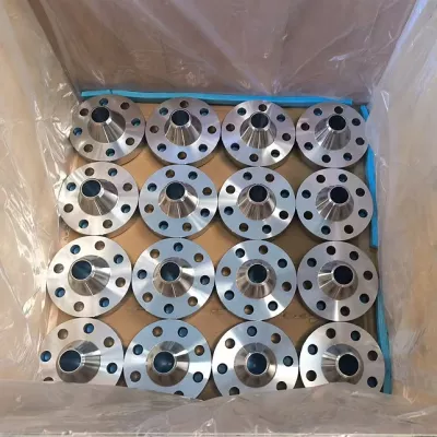
This industrial equipment listing describes a steel weld neck flange with ASTM A694 and F65 references. High Yield Strength and Polished wording also appears in the title. Confirm the actual material package, dimensional drawing and operating requirements before accepting those descriptions for the proposed equipment connection.
Request the F65 material and strength evidence
Specify the required material designation, condition, traceability and applicable material specification edition. Carbon Steel and Alloy Steel weld neck choices are selectable, but generic material names do not verify the F65 reference. Obtain the actual records required for the ordered component.
Ask for the mechanical test and production inspections needed by the purchase specification. High Yield Strength wording does not provide a measured value or an inspection result. Do not use it to assign a numerical strength, pressure class or general high-pressure suitability without the actual acceptance evidence.
Match the weld neck to the equipment pipe
Identify the dimensional standard and edition, then provide nominal size, bore and pipe match, neck geometry, weld preparation, facing and thickness. The material reference alone is not a complete flange drawing. Agree connection and inspection requirements for the actual selected design.
Check the full drilling pattern against the mating flange, including the four half-inch holes stated in the table. Define measurable finish criteria beyond Polished. Confirm the exact material and size combination is available rather than applying one drawing throughout the shared 1/2–120 inch range or across other selectable flange types.
Connect material acceptance with equipment duty
Describe the fluid, contaminants, pressure, temperature, cycles, transients and loads affecting the joint. Assess the supplied material and flange under the equipment requirements. Confirm material, mechanical and dimensional records, neck and end inspections, finish acceptance, marking, preservation, quantity and delivery for the selected component and documentation package.
Technical information for every product inquiry
Prepare the requirement before final product confirmation.
The product page is a starting point. Drawings, samples, interfaces, materials, quantities and acceptance requirements are reviewed before stock matching or custom production is confirmed.
Discuss this product in your project context.
Share the available drawing, sample, reference, target quantity and application information. Unknown items can remain open for review.