
Lap Joint Flange Enquiry for Industrial Piping
For industrial sourcing
Prepare a clearer RFQ
Include the details below so RELIA can understand the part and discuss the next step with you.
- Drawing, sample, or reference standard
- Material grade and preferred process
- Dimensions, tolerances, and surface finish
- Application, target quantity, and destination
Production timing, packing, and shipping terms are confirmed for each project after specifications and trade terms are agreed.
-
Surface TreatmentPolishedApplicationIndustrial Equipment
-
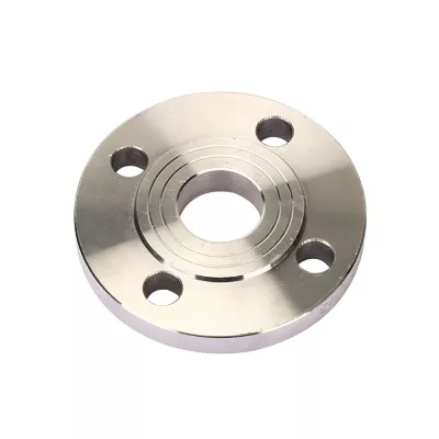
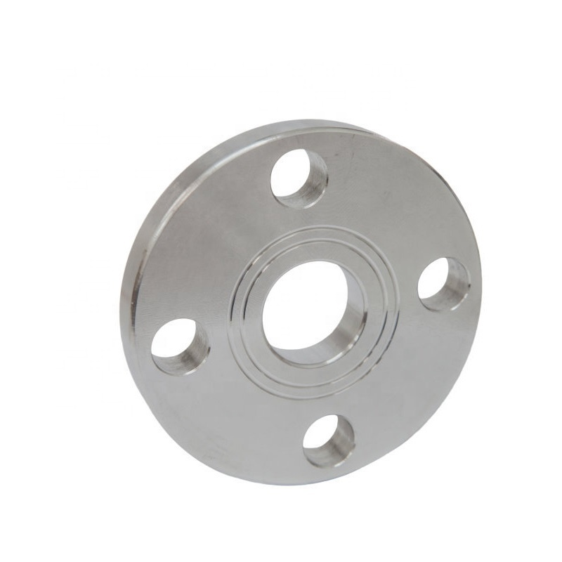
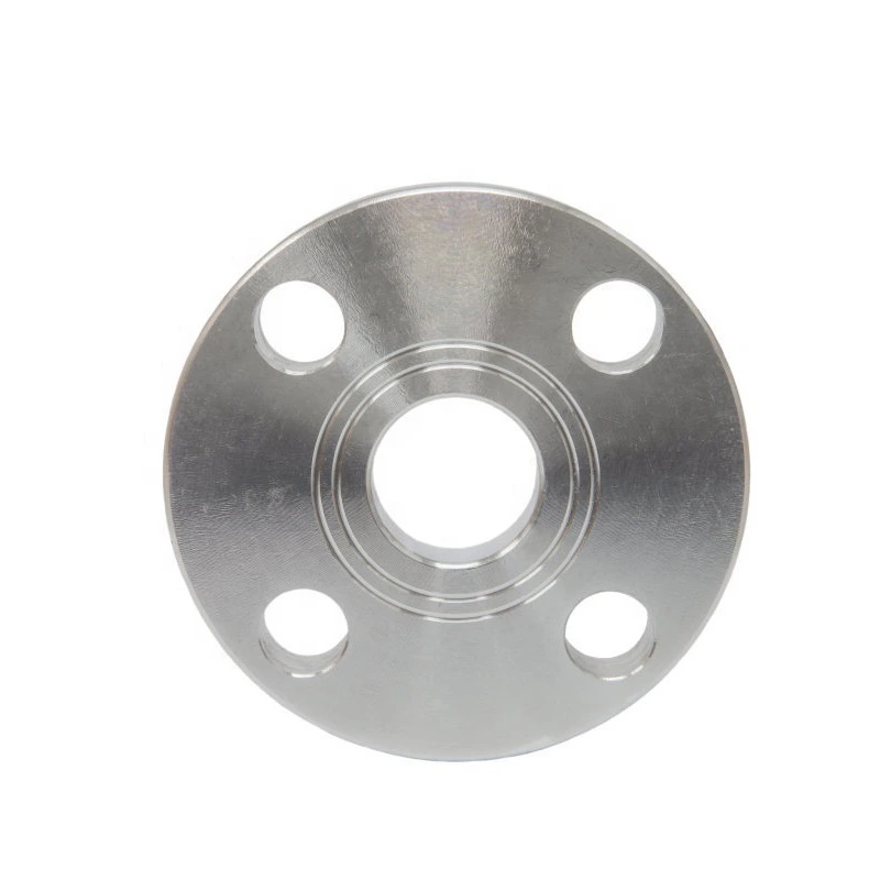
Bolt Hole Diameter1/2"Bolt Hole Quantity4
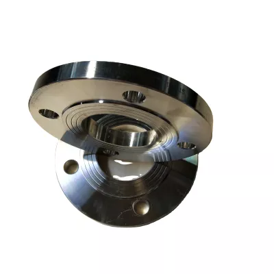
This industrial component listing names a lap joint stub end in the title, while its selectable types include Lap Joint Flange alongside other flange designs. Confirm whether the required supply is the stub end, backing flange or a matched assembly before defining the order.
Identify each component in the lap joint
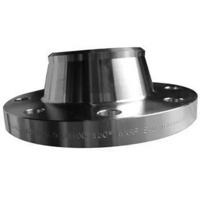
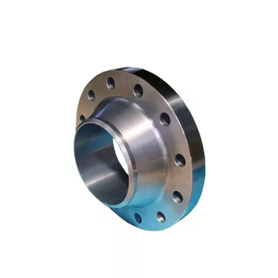
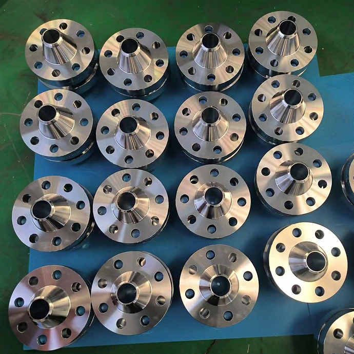
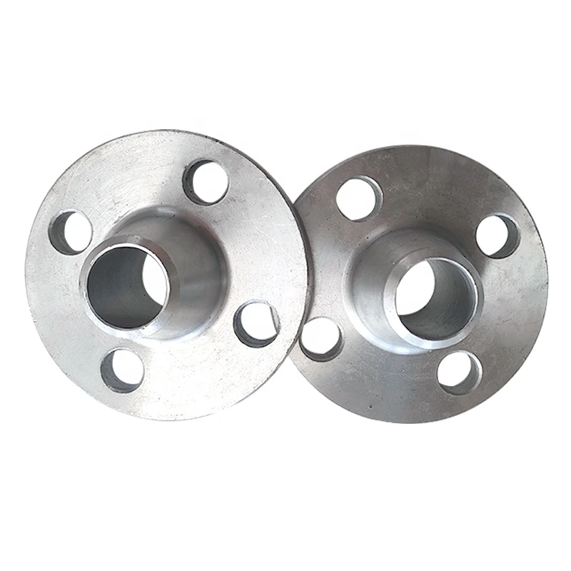
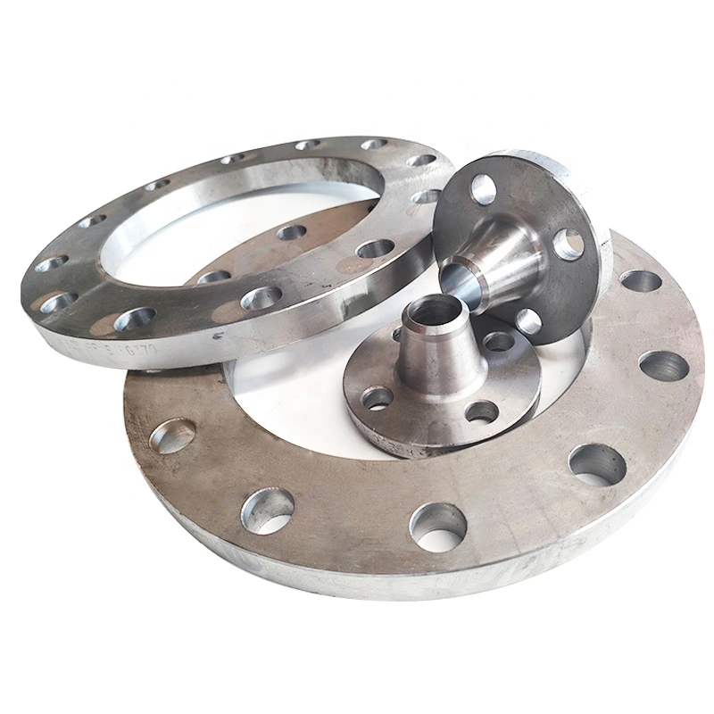
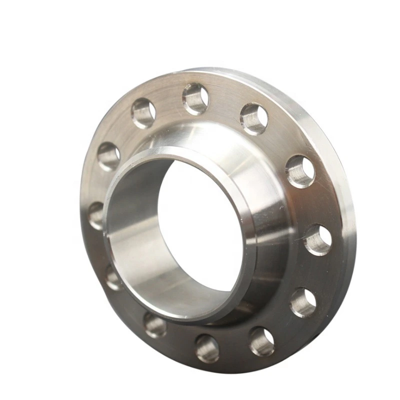
Provide an assembly drawing showing the relationship between the pipe end, lap and flange. Specify the relevant facing, thickness, end dimensions and gasket arrangement for the component being purchased. The original photograph shows necked drilled flanges and does not establish a particular stub end or lap-joint configuration.
The catalog offers Alloy Steel, Aluminum, Carbon Steel and Stainless Steel across nine type labels. Select the actual material and component explicitly. The shared 1/2–120 inch size range does not establish availability or compatibility for every listed type, size and class combination.
Confirm Class 900 and the drilling pattern
The Class 900 title reference does not provide a 900 psi pressure limit. Identify the governing standard and edition for the selected components and their actual pressure-temperature acceptance. ANSI wording alone does not specify a complete dimensional standard.
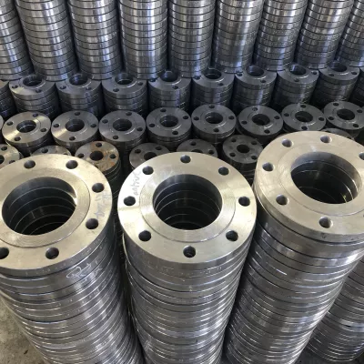
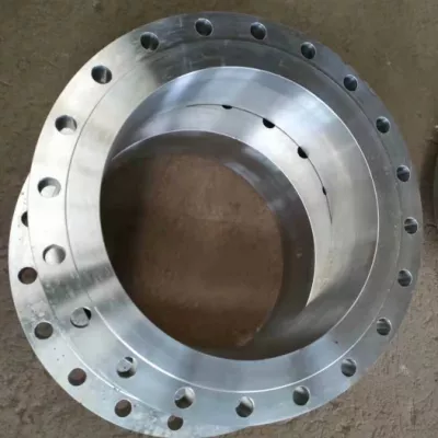
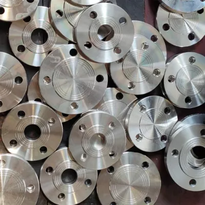
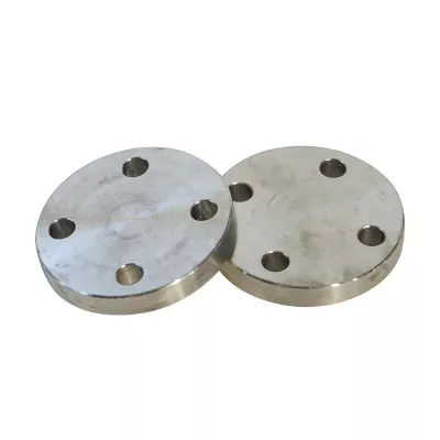
The short table lists four bolt holes with a 1/2-inch diameter, while the image includes flanges with a different visible hole count. Obtain the exact bolt circle, count and hole diameter from the approved drawing. Do not apply the table pattern universally across the broader catalog.
Agree material and assembled joint requirements
Request the actual material grades, conditions, traceability and dimensional inspections for each supplied component. Clarify the required finish beyond Polished and the intended fluid, pressure, temperature, cycles and loads. Review the assembled flange, gasket and bolting design, then confirm marking, preservation, quantity and delivery timing with the final supply specification.
Technical information for every product inquiry
Prepare the requirement before final product confirmation.
The product page is a starting point. Drawings, samples, interfaces, materials, quantities and acceptance requirements are reviewed before stock matching or custom production is confirmed.
Discuss this product in your project context.
Share the available drawing, sample, reference, target quantity and application information. Unknown items can remain open for review.