
Steel Pipe for Industrial Fluid Transportation
For industrial sourcing
Prepare a clearer RFQ
Include the details below so RELIA can understand the part and discuss the next step with you.
- Drawing, sample, or reference standard
- Material grade and preferred process
- Dimensions, tolerances, and surface finish
- Application, target quantity, and destination
Production timing, packing, and shipping terms are confirmed for each project after specifications and trade terms are agreed.
-
InvoicingBy Actual WeightOiled or Non-oiledNon-oiled
-
Section ShapeRoundSurface TreatmentCold Rolled
-
Tolerance±1%Alloy Or NotNon-Alloy
-
ApplicationFluid Pipe, Drill Pipe, Hydraulic Pipe, Gas Pipe, Oil PipeCertificateAPI , ISO 9001
-
Delivery Time8 ~ 14 daysGradestainless steel
-
Outer Diameter219 - 1066 mmSpecial PipeAPI Pipe, Other, EMT Pipe, Thick Wall Pipe
-
StandardASTMTechniqueERW
This steel pipe listing addresses industrial fluid transportation with carbon material and seamless references. The table instead identifies stainless steel and ERW. Establish the actual supplied grade and manufacturing route before deciding whether the pipe meets the requirements of a specific transported fluid.
Define the fluid system and actual operating requirements
Identify the medium, composition, contaminants, pressure, temperature, cycles, environment and external loads. The general fluid, drilling, hydraulic, gas and oil table entries do not establish universal compatibility. State the selected application and joint requirements so that material and dimensional acceptance can be assessed against one defined duty.
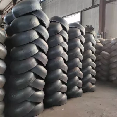
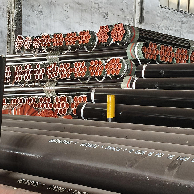
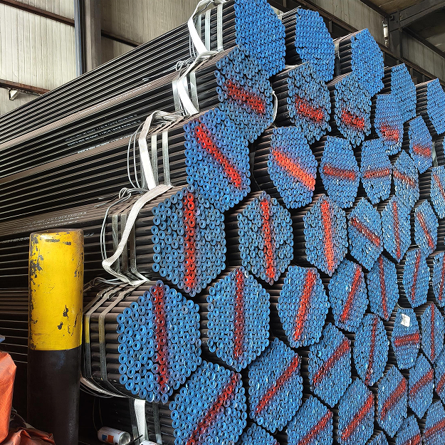
Request the actual specification, grade, condition, traceability and material inspection records. Resolve carbon and stainless descriptions through supply documentation, and establish seamless or ERW production with manufacturing evidence. The original photograph shows bundled round pipes with covered ends and markings; it cannot certify chemistry, route or approval for the chosen fluid.
Specify pipe geometry and the mating connection
The variants list a wall range of 6–20 mm with lengths of 12 m or 6 m. Specify actual outside diameter, bore, wall and length from the installation drawing. Reconcile the 219–1066 mm diameter range with the selected line section and its mating components.
Set end preparation, straightness, roundness and connection criteria. Clarify the dimensional scope of ±1% and the accepted measurement method. Confirm actual Cold Rolled finish, Non-oiled supply, required cleanliness and preservation. End protectors and printed markings do not demonstrate internal condition, dimensional fit or leak performance at the proposed joint.
Agree supplied evidence and fluid-line acceptance tests
Identify the applicable ASTM specification, edition, product coverage and project conformity requirements. Review the verified grade, condition, construction and geometry against the defined fluid duty. Agree material, dimensional, surface, end and required system tests with criteria and traceable reports. Generic API and ISO 9001 labels establish no numerical pressure limit, corrosion guarantee or service-life promise.
Technical information for every product inquiry
Prepare the requirement before final product confirmation.
The product page is a starting point. Drawings, samples, interfaces, materials, quantities and acceptance requirements are reviewed before stock matching or custom production is confirmed.
Discuss this product in your project context.
Share the available drawing, sample, reference, target quantity and application information. Unknown items can remain open for review.