
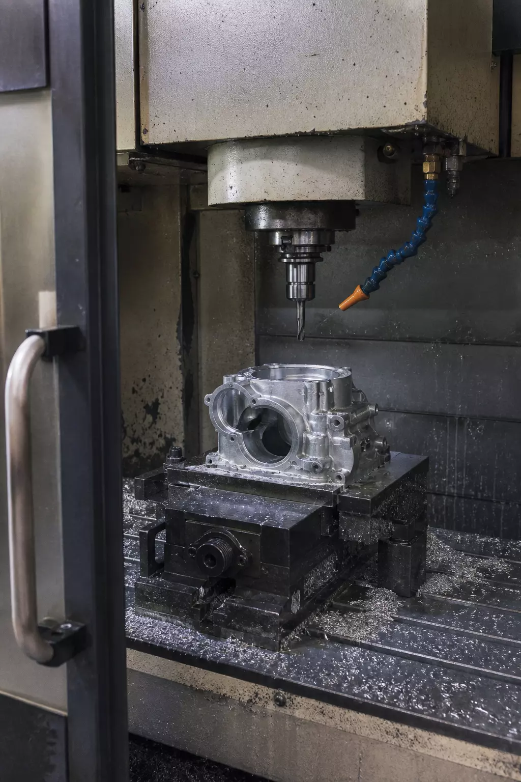
Custom Bends and Return Elbows for Equipment OEMs
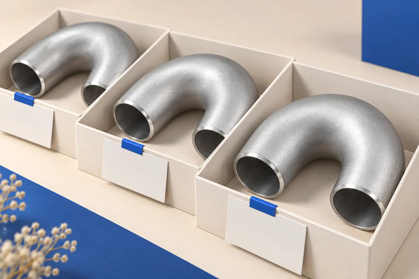
When a standard elbow does not fit your equipment, the useful starting point is the complete path between the connections. We review your custom bend around its end positions, straight lengths and assembly envelope, so the quotation describes the part you intend to install.
Send your project details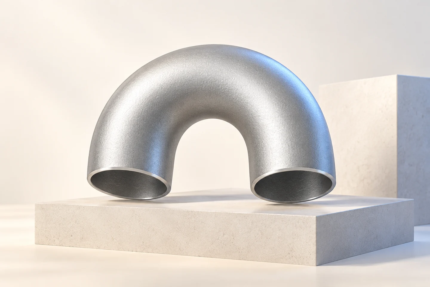
The complete path defines the part
An angle and a pipe diameter leave much of a custom bend undefined. Your drawing should connect the bend radius, straight portions and end directions to a common reference. We retain those relationships when reviewing the supply configuration.
- PathAngle and radius
- EndsPosition and direction
- EnvelopeEquipment clearance
End positions matter as much as the curve
Two bends can share an angle and still reach different connection points. We need your end coordinates, tangent lengths and reference datums. These details give both teams the same assembly target before the first part is discussed.
A clear definition for every formed feature
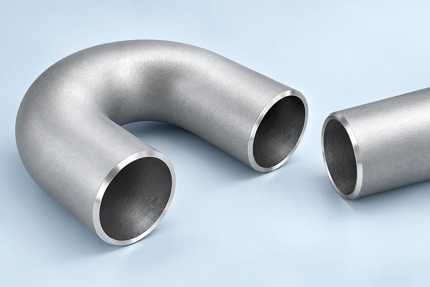
Keep the base tube, required wall, end preparation and surface state separate from the bend geometry. We review each requirement rather than filling gaps from a catalogue application name. A product described for an equipment outlet does not establish compatibility with your assembly.
Catalogue reference. The approved specification defines the supplied configuration.Manufacturing feasibility before release
Your requested path needs a review of forming, tooling and finishing requirements. We identify the proposed supply scope and the constraints that need agreement. Any change to the drawing is returned for approval, rather than introduced as an unnoticed manufacturing adjustment.
- ReviewForming and tooling inputs
- ClarifyConstraints and proposed deviations
- AgreeAccepted supply geometry
The formed section receives its own checks
The finished bend is the part your equipment receives. We agree the critical section, wall and end-position checks against your acceptance requirements. A visually smooth curve is helpful for illustration, while measured results support the decision to accept the formed part.
First-article evidence with a defined scope
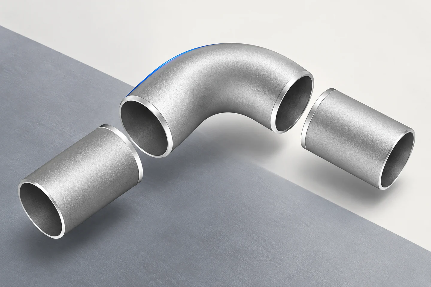
Your first-article review can combine dimensional results and an agreed assembly check. We keep the drawing revision and material identity attached to that review. The approval should state what has been accepted, without turning one trial fit into a general performance claim.
- DrawingControlled revision
- MeasurementCritical feature results
- AssemblyAgreed trial conditions
- ApprovalRecorded acceptance scope
A shared route through clarification
You define the equipment interfaces and the design limits. We review the supply route and identify open manufacturing details. Together, we close the geometry and verification points before release, helping purchasing avoid an order that is clear commercially but incomplete technically.
- YouDefine the equipment interface
- WeClarify the manufacturing proposal
- TogetherApprove the part baseline
Repeat orders retain the accepted shape
A successful first part becomes more useful when its configuration remains controlled. We use the approved drawing as the repeat reference and review proposed changes with you. Identification and agreed protection help your receiving team keep different bend paths separate.
A clear start for your quotation
Send a dimensioned drawing or model with datums, end coordinates, bend radius, straight lengths, material, wall and surface requirements. Add sample and production quantities and your acceptance needs so we can review the custom configuration.
Send your project details- SendDrawing, item list and requirements
- ReviewConfiguration, open points and records
- AgreeTechnical scope and commercial basis