
Slip-On and Weld-Neck Flanges for Pump Skids
Choose the flange arrangement around the pump nozzle and the way the skid will be welded and inspected. A slip-on flange fits over the pipe, while a weld-neck flange connects through its prepared neck and butt-weld end; neither becomes interchangeable simply because the nominal size matches. RELIA manufactures and machines these flange configurations. This guide compares their interfaces, fabrication access and approval needs so your team can freeze the right connection before repeat skid production.
Discuss this purchase with RELIA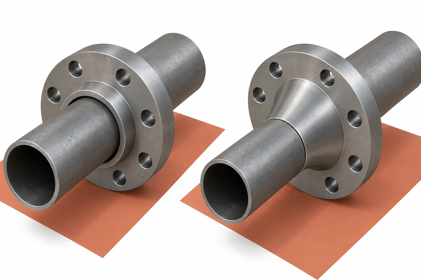
RELIA Flange Manufacturing for Pump-Skid OEMs
RELIA manufactures forged and machined flange components in China. For a pump-skid OEM, the relevant capability is making the selected interface consistently after the engineering choice has been frozen. We review the flange form, pipe-side geometry, sealing face and drilling as one part definition. The skid design, supports, welding procedure and system validation remain with the responsible project team; our component review supports that engineering baseline.
- RELIA in ChinaIn-house flange forging and machining
- Your benefitThe blank and finished interface reviewed together
- Initial checksDimensions, material documents and pre-shipment condition
The pump interface determines the connection
Start by identifying the pump nozzle, adjacent pipe and available assembly space. A slip-on flange fits over the pipe; a weld-neck flange connects through its neck and prepared butt-weld end. This structural difference changes the fabrication details even if both items share the same nominal size.
Our catalogue includes an A105 slip-on enquiry and a DN150 / NPS 6 A105 Class 150 weld-neck reference. Use these as separate candidates and match their full interfaces before treating either as an OEM part.
Catalogue references support the enquiry. The accepted drawing, material definition and quotation identify the supplied configuration.
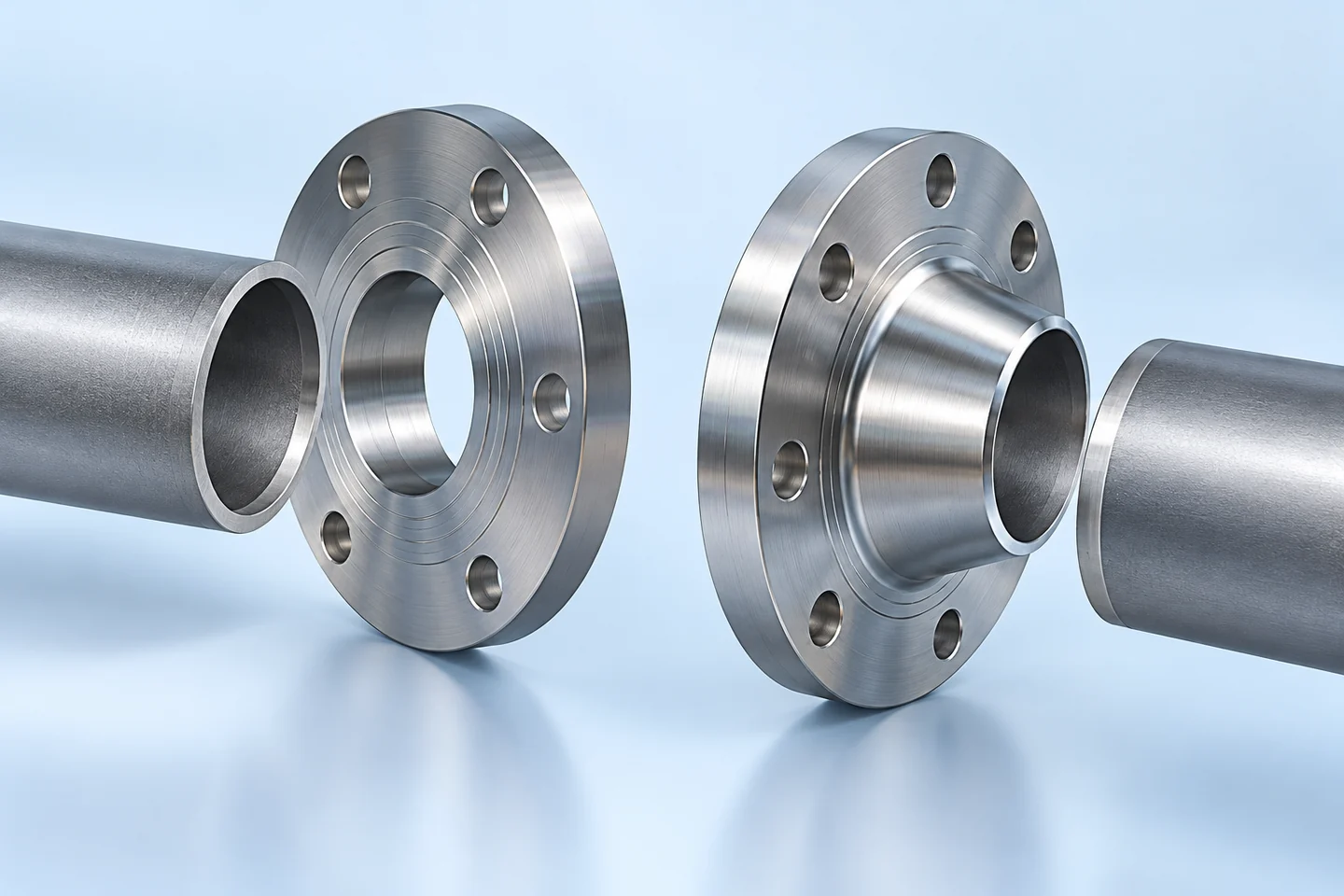
Slip-on and weld-neck layouts differ
In a slip-on arrangement, the pipe position and the approved joining detail need room within the flange assembly. In a weld-neck arrangement, the bore, neck transition and pipe wall meet at the prepared end. The correct choice depends on the approved joint design and fabrication plan, not a general price ranking.
Before ordering, review access for welding, inspection, bolts and tools. A connection that fits a three-dimensional envelope can still be difficult to fabricate in the proposed sequence.
| Parameter | Purchase meaning |
|---|---|
| Pipe interface | Insertion arrangement versus butt-weld transition |
| Fabrication | Joining access and assembly order |
| Inspection | Access required by the project method |
| Maintenance | Bolt and removal clearance |
Machining features follow the selected flange form
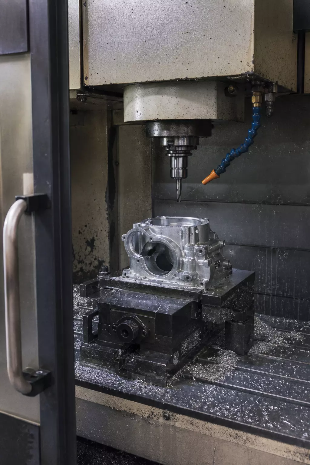
The flange form determines what the machining operation needs to establish. A slip-on component needs the accepted entry bore and face relationship; a weld-neck component needs the neck and end transition as well. Both need the mating face and bolt pattern produced from the correct reference.
RELIA connects the forging blank with the machining plan. That review can identify insufficient stock, difficult clamping or a critical dimension that lacks a clear datum before the drawing enters repeat production.
- BlankStock suited to the selected flange form
- DatumsReferences shared by machining and inspection
- Functional featuresPipe side, face and drilling
- ReleaseAgreed drawing and identified open points
Space for fabrication and inspection
Treat the assembly envelope as a measured design input. Show the pump-nozzle face, pipe axis, nearby supports and the space needed to insert or remove bolts. Add the welding and inspection access that the fabrication procedure actually requires.
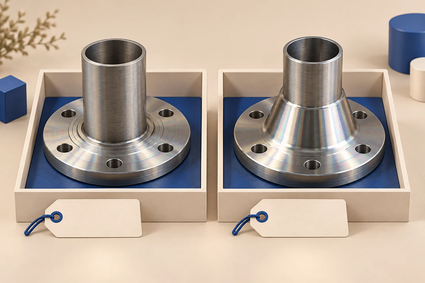
The concept image compares flange structures only. It does not establish a completed joint detail or a validated pump-skid assembly. Use the equipment drawing and accepted joining detail to define the manufactured component.
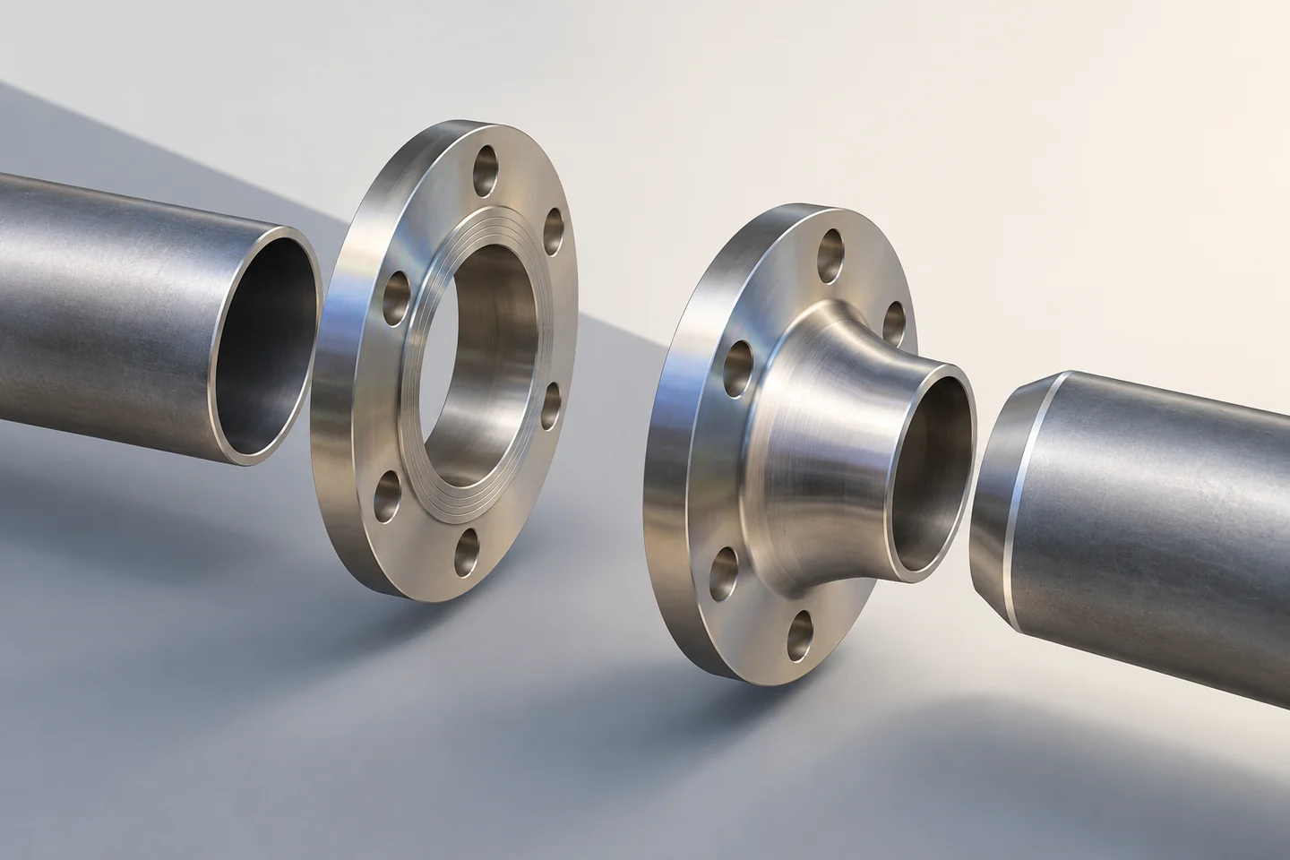
Joint features checked against the assembly
Acceptance needs to answer whether the component matches the frozen interface. Record the bore or entry diameter, face, thickness, drilling and the relevant neck/end features with units. Check the material documents separately against the specified grade.
An agreed first-article fit check can help the OEM review installation, but it does not replace pressure-design approval or validation of the complete skid. State the scope of sample acceptance so later orders use it correctly.
| Parameter | Purchase meaning |
|---|---|
| Dimensions | Features identified on the accepted component drawing |
| Material | Specified grade and relevant documents |
| Assembly | Trial fit only where agreed |
| Scope | Component acceptance distinct from system validation |
A drawing baseline for the OEM team
The most useful evidence package joins the OEM part number, drawing revision, material and measured features. For RELIA, a genuine machining photo or anonymised dimension record can explain how the component is made and checked. It should refer to the configuration under discussion.
The A105 project guide addresses execution of an already specified flange order. This page serves the earlier OEM choice between structures; the pump-suction reducer guide addresses a different adjacent component decision.
- OEM inputNozzle drawing and assembly constraints
- Factory outputManufacturing definition and inspection basis
- Joint decisionAccepted flange form and revision
- Next enquiryRepeat quantity against the same reference
The accepted interface carries into repeat production
Once the interface is accepted, keep the flange form and pipe-side requirements visible in the BOM and delivery identification. Avoid grouping SO and WN variants under a single ambiguous line. Their materials and nominal sizes may look similar while their fabrication details differ.
RELIA can review repeat orders against that accepted component definition. Proposed changes should be visible before manufacture so purchasing can coordinate them with the equipment team.
Contact RELIA for Your Purchase Specification
Send the pump/nozzle drawing, pipe outside diameter and wall, flange candidates, facing and drilling standard, assembly clearances and joining requirements. Add sample and repeat quantities so RELIA can review the component definition.
- DefineDrawing, configuration and quantities
- ReviewManufacturing scope and inspection requirements
- QuoteA clear technical and commercial basis