

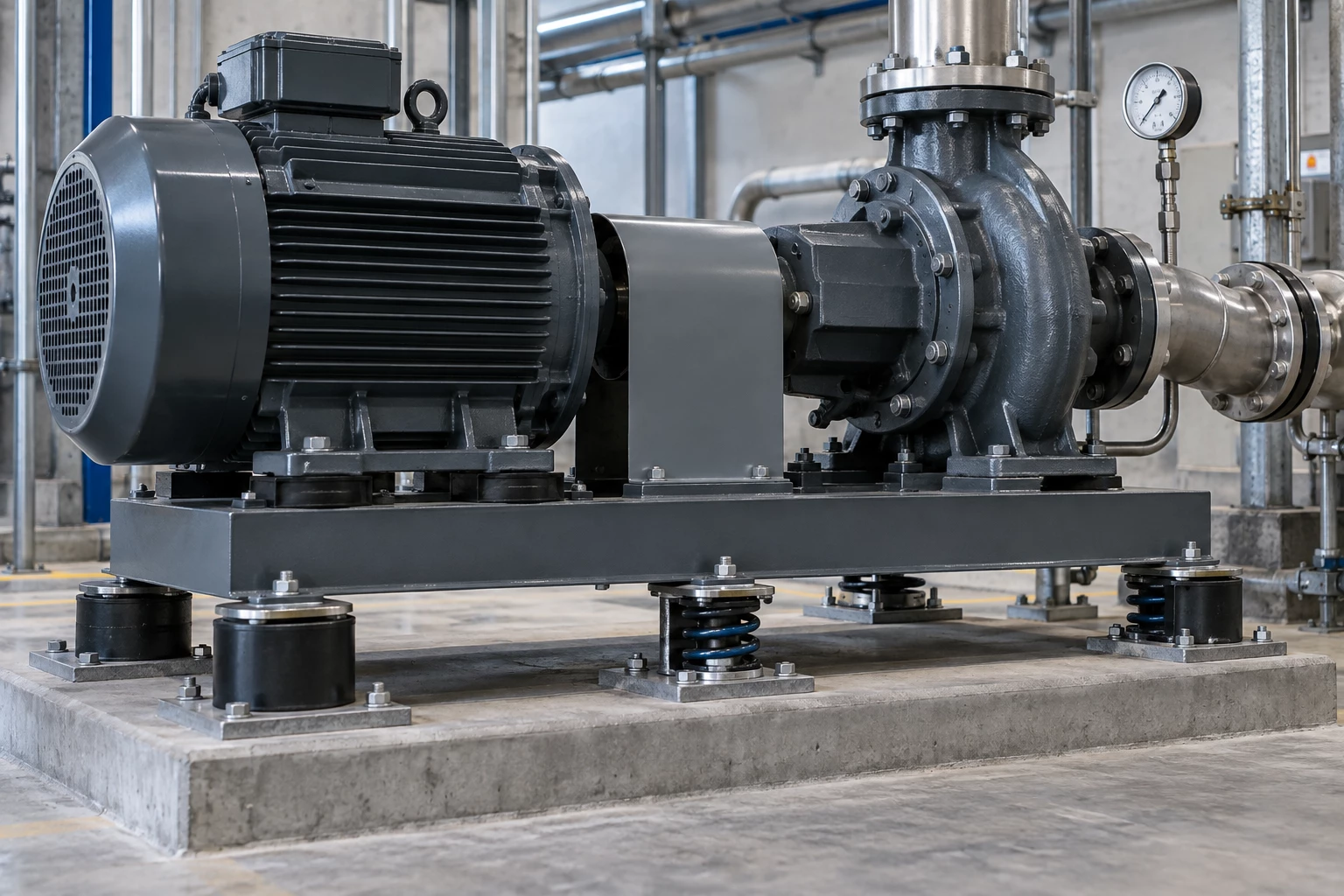
Return to Isolator Load, Deflection and Frequency
The total equipment weight does not automatically divide equally among mounts. Center of gravity, base stiffness, accessories and connected services can make one point carry substantially more load.
Start with point loads, not an average
For why load distribution matters in vibration isolation, record each input with its unit, source and current status. Known values can be used immediately; unknown values should remain visible for confirmation instead of becoming silent quotation or production assumptions.
Connect load distribution to deflection and frequency
Size each mount for its actual supported load
Show where forces and movement enter the surrounding system. A connector or isolator cannot be reviewed independently when anchors, guides, supports or rigid services control its real behavior. For this check, connect “Size each mount for its actual supported load” to operating weight.
Compare installed deflection across all points
State each direction and magnitude separately, then identify simultaneous movement and cycle pattern. Installation offset and operating travel are different demands and should not consume the same allowance unnoticed. For this check, connect “Compare installed deflection across all points” to center of gravity or point loads.
Check that the base does not twist between mounts
For isolator load, deflection and frequency, connect this check to a drawing, measurement, photograph or acceptance note. Mark the remaining decision as open instead of allowing it to become an unstated quotation assumption. For this check, connect “Check that the base does not twist between mounts” to mount locations.
Keep rigid services from bypassing the isolation path
Trace every physical connection around the isolation system. A stiff pipe, duct, cable, guard or shipping restraint can transmit force even when the selected mounts are correctly loaded. For this check, connect “Keep rigid services from bypassing the isolation path” to running speed/frequencies.
Shortcuts that distort an isolator selection
- Dividing total weight equally without evidence. Obtain point loads or the best available load distribution from the equipment geometry and center of gravity. Keep uncertainty visible when a precise calculation is not yet available. Record the correction point against operating weight.
- Selecting every mount from the same nominal capacity. Use the catalog or appearance only to narrow the route. Confirm the actual function, interface, operating duty and governing standard before treating the candidate as a match. Record the correction point against center of gravity or point loads.
- Ignoring fluid charge, belts, motors or attached equipment. Replace the shortcut with a visible assumption register for isolator load, deflection and frequency. Confirm the unknown through the buyer, drawing, sample or agreed inspection method before release. Record the correction point against mount locations.
Build the supported-system picture
Collect operating weights.
Start with operating weight and center of gravity or point loads. Include the governing drawing, sample, equipment reference or application context that explains where the information came from.
Calculate or measure point reactions.
Separate confirmed values from open items, especially mount locations and running speed/frequencies. This allows an early review without turning missing information into guessed requirements.
Select mounts by point load and required deflection.
Compare the route against each mount carries its actual share of operating load and static deflection relates to system natural frequency. Record why one option is being advanced and what evidence is still needed.
Level, commission and verify installed condition.
Carry the same approved isolator load, deflection and frequency revision, assumptions and acceptance criteria into quotation, sample review, production, inspection, packing and repeat orders.
RELIA can review the available information for why load distribution matters in vibration isolation, identify open items, and compare stock matching with custom production. Final product configuration and acceptance remain tied to the approved project information.
Send the current information for a project-specific review
You do not need to guess missing values before making contact about why load distribution matters in vibration isolation. Send the confirmed information and mark the remaining decisions for discussion.