
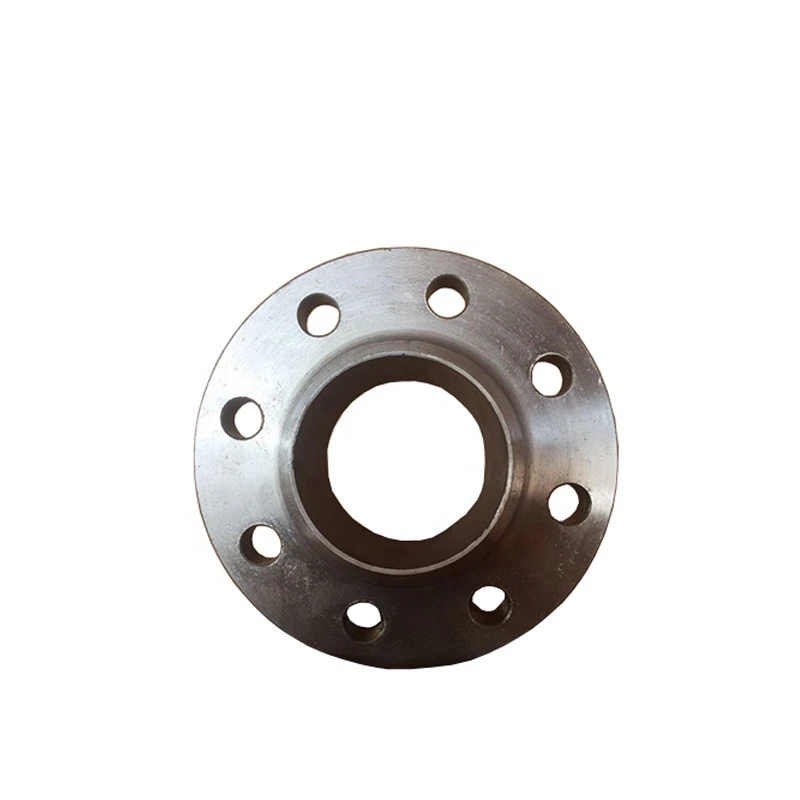
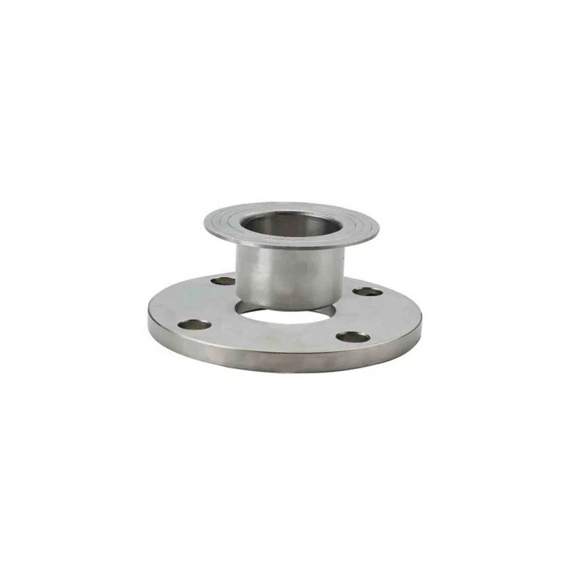
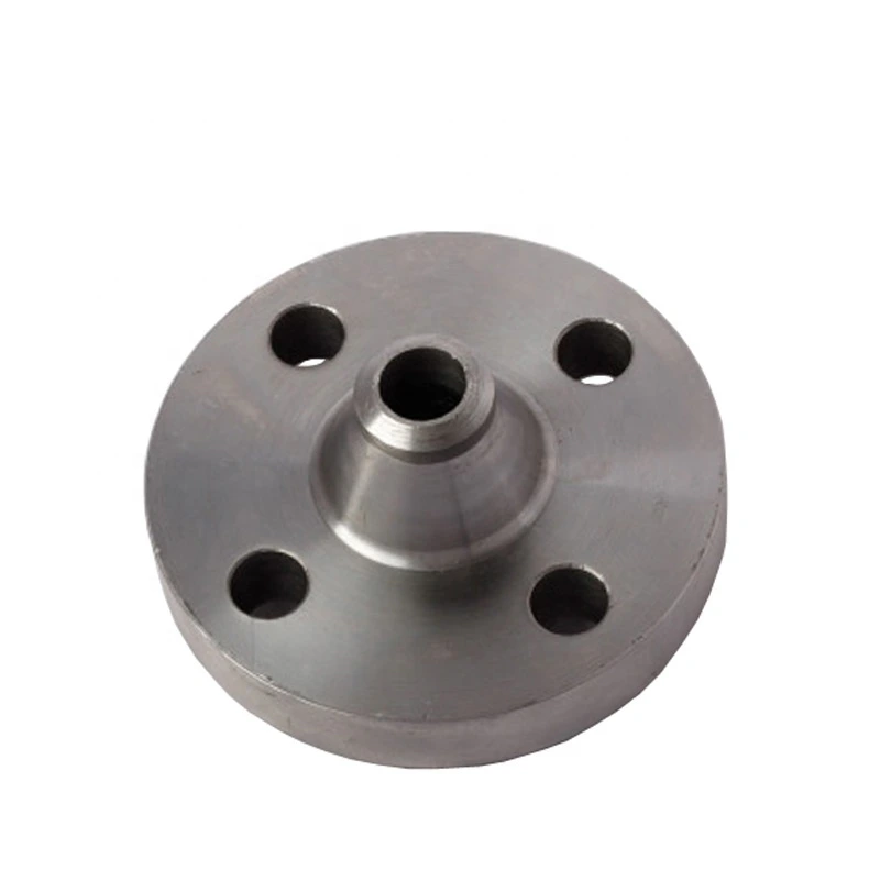
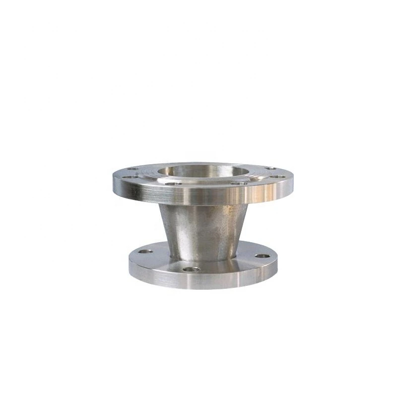
ASTM A694 F65 Weld Neck Flange for Equipment
Voor industriële inkoop
Bereid een duidelijke RFQ voor
Neem onderstaande gegevens op zodat RELIA het onderdeel begrijpt en de volgende stap kan bespreken.
- Tekening, monster of referentienorm
- Materiaalkwaliteit en voorkeursproces
- Maten, toleranties en oppervlakteafwerking
- Toepassing, doelvolume en bestemming
Productietijd, verpakking en verzendvoorwaarden worden per project bevestigd nadat specificaties en handelsvoorwaarden zijn overeengekomen.
-
Surface TreatmentPolishedApplicationIndustrial Equipment
-
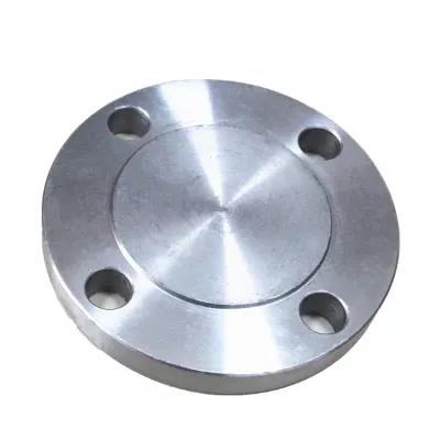
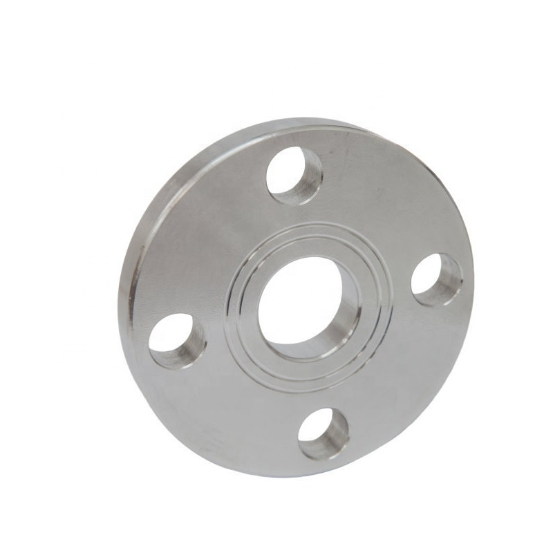
Bolt Hole Diameter1/2"Bolt Hole Quantity4
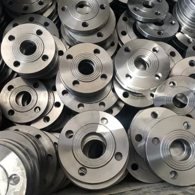
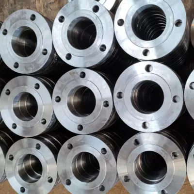
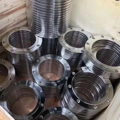
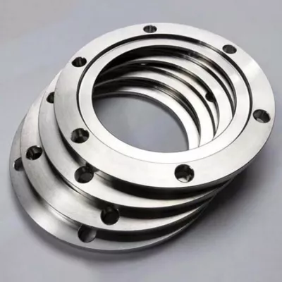
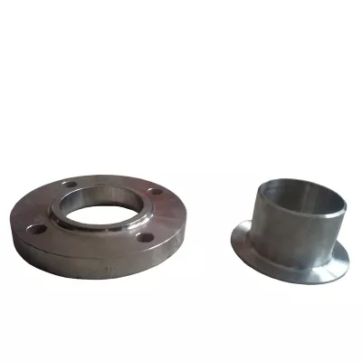
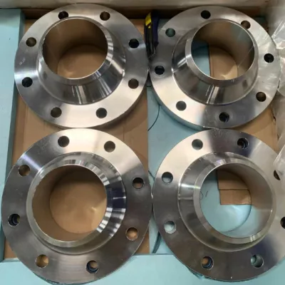
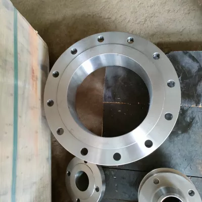
This industrial equipment listing describes a steel weld neck flange with ASTM A694 and F65 references. High Yield Strength and Polished wording also appears in the title. Confirm the actual material package, dimensional drawing and operating requirements before accepting those descriptions for the proposed equipment connection.
Request the F65 material and strength evidence
Specify the required material designation, condition, traceability and applicable material specification edition. Carbon Steel and Alloy Steel weld neck choices are selectable, but generic material names do not verify the F65 reference. Obtain the actual records required for the ordered component.
Ask for the mechanical test and production inspections needed by the purchase specification. High Yield Strength wording does not provide a measured value or an inspection result. Do not use it to assign a numerical strength, pressure class or general high-pressure suitability without the actual acceptance evidence.
Match the weld neck to the equipment pipe
Identify the dimensional standard and edition, then provide nominal size, bore and pipe match, neck geometry, weld preparation, facing and thickness. The material reference alone is not a complete flange drawing. Agree connection and inspection requirements for the actual selected design.
Check the full drilling pattern against the mating flange, including the four half-inch holes stated in the table. Define measurable finish criteria beyond Polished. Confirm the exact material and size combination is available rather than applying one drawing throughout the shared 1/2–120 inch range or across other selectable flange types.
Connect material acceptance with equipment duty
Describe the fluid, contaminants, pressure, temperature, cycles, transients and loads affecting the joint. Assess the supplied material and flange under the equipment requirements. Confirm material, mechanical and dimensional records, neck and end inspections, finish acceptance, marking, preservation, quantity and delivery for the selected component and documentation package.
Technische informatie voor elke productaanvraag
Bereid de eis voor vóór de definitieve productbevestiging.
De productpagina is het startpunt. Tekeningen, monsters, interfaces, materialen, aantallen en acceptatie-eisen worden beoordeeld vóór voorraadmatch of maatwerkproductie.
Bespreek dit product binnen uw project.
Deel tekening, monster, referentie, doelaantal en toepassing. Onbekende punten kunnen openblijven voor beoordeling.