Slip-On and Weld-Neck Flanges for Pump Skids
Your flange choice has to fit the pump nozzle, the pipe and the way the skid will be assembled. We help you turn the approved connection arrangement into a clear supply requirement. Slip-on and weld-neck configurations stay separate until the design and fabrication inputs support the intended choice.
Send your project details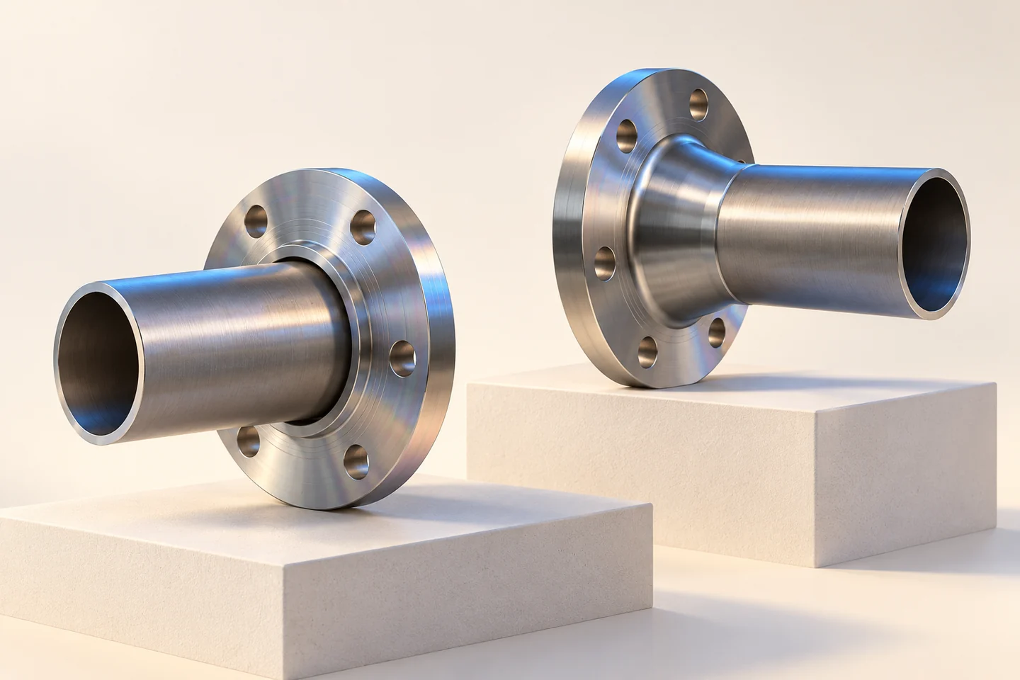
Start with both sides of the connection
The pump nozzle and the connecting pipe describe different parts of the interface. Keep the equipment drawing, pipe dimensions and mating-flange information together. We review the proposed flange against that combined set, helping you avoid a choice based on nominal size alone.
- PumpNozzle drawing
- PipeDiameter and wall requirement
- JointMating flange and facing
The flange form follows the approved design
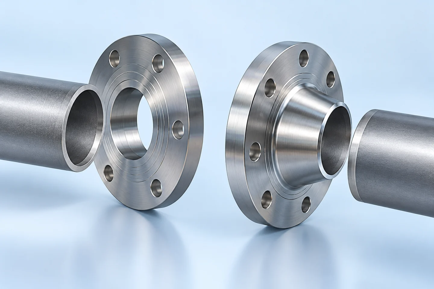
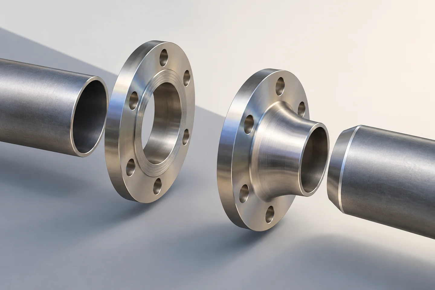
Slip-on and weld-neck arrangements bring different geometry to the connection. The useful comparison is the one tied to your approved piping requirements and fabrication conditions. We review the specified form and flag departures; the purchasing description does not replace your engineering approval.
Space for welding and inspection
A flange may fit the drawing outline while leaving poor access for the planned work. Your assembly review should include tool space, weld access and inspection access. We retain the relevant dimensional limits with the enquiry, so the supply configuration supports the fabrication sequence you intend.
Catalogue reference. The approved specification defines the supplied configuration.The complete joint stays in view
The flange, gasket, bolting and equipment nozzle form one connection. We keep the matching requirements visible rather than quoting the flange as an isolated shape. Any change in facing, drilling or bore is reviewed against the complete interface before it becomes an order change.
- InputsMating components
- ReviewFacing, drilling and bore
- ReleaseApproved joint configuration
An interface drawing reduces assumptions
A clear drawing identifies the dimensions that both the equipment and piping teams need to recognise. We work from the approved nozzle and pipe information and agree the critical checks. A trial fit can support the dimensional review while the service and design requirements retain their own approval basis.
Evidence matched to the selected form
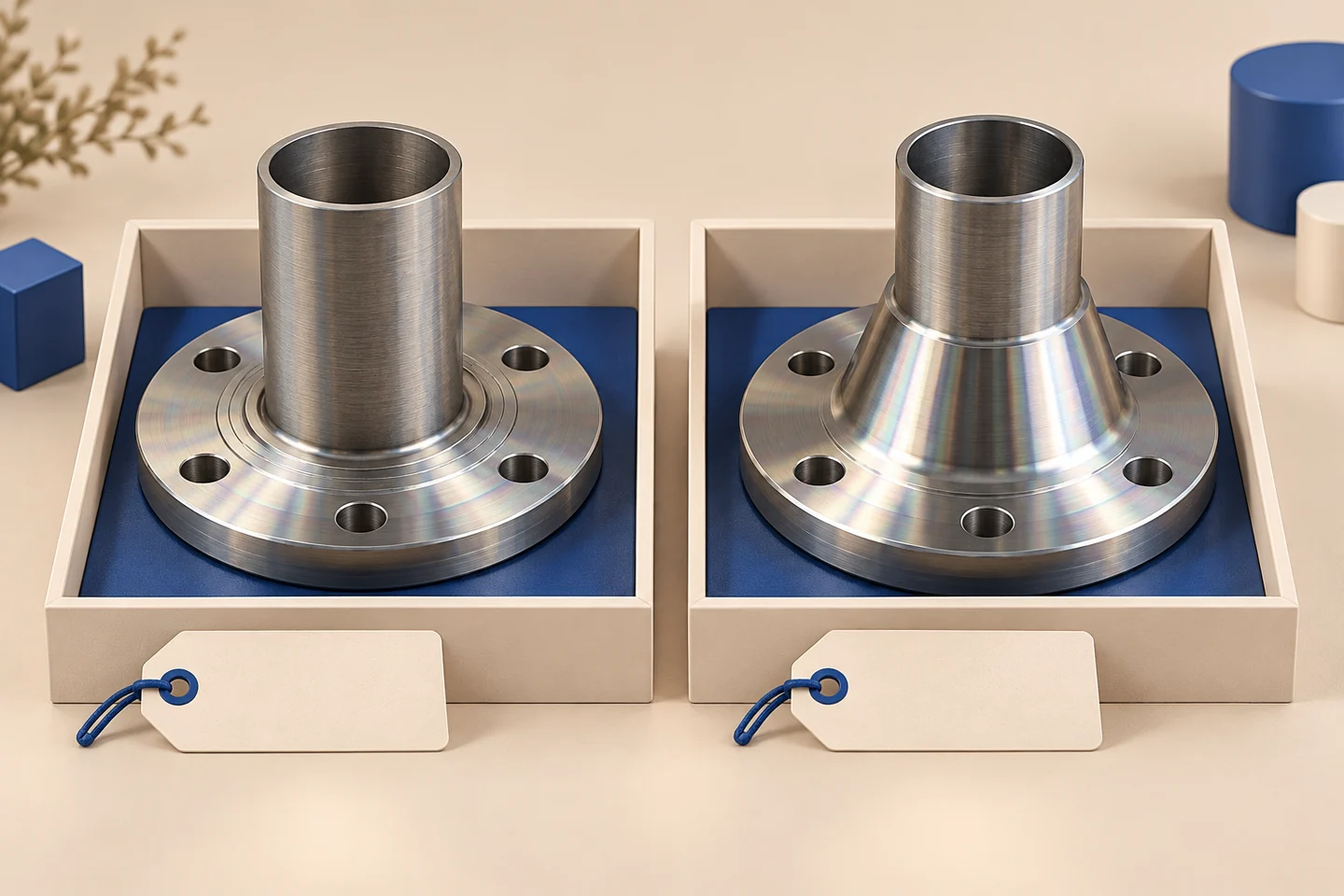
Your record list should follow the flange actually quoted. We agree material identification, dimensional reporting and any specified additional inspection. This keeps a weld-neck reference from being used as evidence for a different slip-on item, even when both share a size or material family.
- TypeQuoted flange form
- MaterialSpecified identity
- GeometryRelevant measured features
- RecordsItem-specific scope
A shared design-freeze point
You confirm the equipment and piping requirements. We clarify the manufacturable supply configuration and open points within our offer. Together, we retain the accepted part definition before repeat purchasing starts, so procurement has a clear reference when the skid design evolves.
- YouApprove the joint requirements
- WeClarify the supply configuration
- TogetherFreeze drawing and item reference
A repeat BOM that preserves the interface
A repeat order is easier to manage when the flange type and connection details remain attached to the equipment item code. We review proposed alternatives as changes, not silent equivalents. The agreed packing and identification scope supports receiving checks before the flange reaches assembly.
A clear start for your quotation
Send the pump nozzle drawing, pipe outside diameter and wall, approved flange arrangement, facing and drilling requirements, assembly limits and quantities. Include your inspection and first-assembly needs so we can review the complete supply configuration.
Send your project details- SendDrawing, item list and requirements
- ReviewConfiguration, open points and records
- AgreeTechnical scope and commercial basis